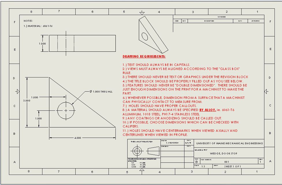

Modern engineering drawing, with its precise conventions of orthographic projection and scale, arose in France at a time when the Industrial Revolution was in its infancy. Complex technical drawings were made in renaissance times, such as the drawings of Leonardo da Vinci. Technical drawing has existed since ancient times.

Only the information that is a requirement is typically specified. Drawings typically contain multiple views of a component, although additional scratch views may be added of details for further explanation. The process of producing engineering drawings is often referred to as technical drawing or drafting ( draughting). Although mostly consisting of pictographic representations, abbreviations and symbols are used for brevity and additional textual explanations may also be provided to convey the necessary information. The drawings are linked together by a master drawing or assembly drawing which gives the drawing numbers of the subsequent detailed components, quantities required, construction materials and possibly 3D images that can be used to locate individual items. Usually, a number of drawings are necessary to completely specify even a simple component. A common use is to specify the geometry necessary for the construction of a component and is called a detail drawing. Engineering drawing of a machine tool partĪn engineering drawing is a type of technical drawing that is used to convey information about an object. If you set the Country to German or France).īritish Standards are supplying a book which provides clear information on the application of BS 8888īIP 2155:2009 The Essential Guide to Technical Product Specification: Engineering Drawing. Point to display as a comma on the regional settings on the control panel (This option is available
#DRAWING STANDARD NOTES PC#
For Autocad drawings on a Windows based PC it is most convenient set the decimal With each group of three digits from the decimal provided with a space e.g. In BS 8888 the decimal place is indicated with a comma In BS308 the decimal place is indicated with aĭecimal point. Orthographic/Axonometric representation,Īn important difference between BS 308 and BS 8888 is in the marking of.Representation of Engineering components,.BS 8888 references standards covering all aspects of technical product Most designers and engineers should have no difficulty in working to the new Technical Product Documentation (it references them).
#DRAWING STANDARD NOTES ISO#
This standard is provided to unify all of the recently implemented ISO and EN ISO standards related to Drawing conventions which applied to BS 308-1'2'3 in generalĪlso apply to the European Standards referenced in BS 8888. Note: The current edition is BS 8888:2011 Specification for defining, specifying and graphically representing products. BS 8888 Technical Product Documentation (TPD) It is also possible to become a BSI member and obtain copies of the Standards at much reduced prices. To confirm the status of any standard, identify the replacement standard if it is obsolete and/or purchase the standard please use BSI Shop.


 0 kommentar(er)
